Product Description
|
Our Company
ZheJiang CHINAMFG Machinery Manufacture Co., Ltd.
–Branch of CHINAMFG Industry Ltd.
We specialize in Metal Parts Solution for Vehicle, Agriculture machine, Construction Machine, transportation equipment, Valve and Pump system.
With keeping manufacturing process design, quality plHangZhou, key manufacturing processes and final quality control in house.
We are mastering key competence to supply quality mechanical parts and assembly to our customers for both Chinese and Export Market.
To satisfy different mechanical and functional requirements from our customers we are making a big range of metal products for our clients on base of different blanks solutions and technologies.
These blanks solutions and technologies include processes of Iron Casting, Steel Casting, Stainless Steel Casting, Aluminum Casting and Forging.
During the early involvement of the customer’s design process we are giving professional input to our customers in terms of process feasibility, cost reduction and function approach.
You are welcome to contact us for technical enquiry and business cooperation.
FAQ:
1. Are you a manufacturer or a trading company?
We are a professional manufacturer with over 15 years’ export experience for designing and producing vehicle machinery parts.
2. How can I get some samples?
If you need, we are glad to offer you samples for free, but the new clients are expected to pay the courier cost,
and the charge will be deducted from the payment for formal order.
3. Can you make casting according to our drawing?
Yes, we can make casting according to your drawing, 2D drawing, or 3D cad model. If the 3D cad model can be supplied,
the development of the tooling can be more efficient. But without 3D, based on 2D drawing we can still make the samples properly approved.
4. Can you make casting based on our samples?
Yes, we can make measurement based on your samples to make drawings for tooling making.
5. What’s your quality control device in house?
We have spectrometer in house to monitor the chemical property, tensile test machine to control the mechanical property and UT Sonic as NDT checking method to control the casting detect under the surface of casting
/* January 22, 2571 19:08:37 */!function(){function s(e,r){var a,o={};try{e&&e.split(“,”).forEach(function(e,t){e&&(a=e.match(/(.*?):(.*)$/))&&1
| Casting Method: | Investment Casting |
|---|---|
| Casting Form Material: | G25crmo4, G35, Wcb |
| Casting Metal: | Cast Steel |
| Casting Form Usage Count: | Permanent |
| Surface Treatment: | Dacromat Coating, Finish Painting |
| Surface Roughness: | 0.005mm-0.01mm-0.1mm |
| Samples: |
US$ 4.56/kg
1 kg(Min.Order) | |
|---|
| Customization: |
Available
| Customized Request |
|---|

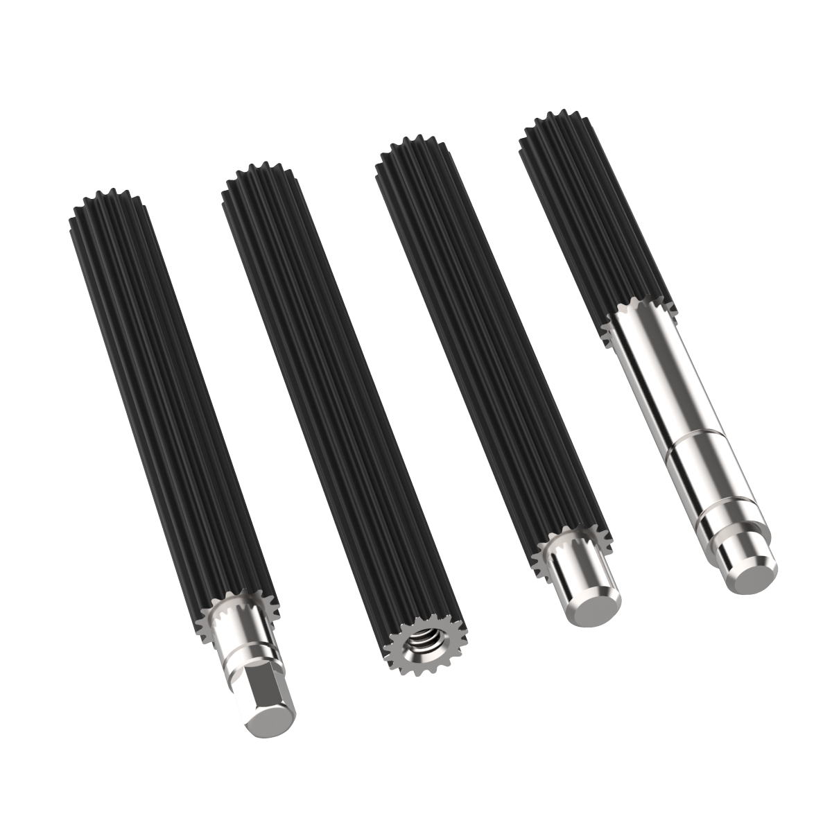
How does the design of a spline shaft affect its performance?
The design of a spline shaft plays a crucial role in determining its performance characteristics. Here’s a detailed explanation:
1. Torque Transmission:
The design of the spline shaft directly affects its ability to transmit torque efficiently. Factors such as the spline profile, number of splines, and engagement length influence the torque-carrying capacity of the shaft. A well-designed spline profile with optimized dimensions ensures maximum contact area and load distribution, resulting in improved torque transmission.
2. Load Distribution:
A properly designed spline shaft distributes the applied load evenly across the engagement surfaces. This helps to minimize stress concentrations and prevents localized wear or failure. The design should consider factors such as spline profile geometry, tooth form, and surface finish to achieve optimal load distribution and enhance the overall performance of the shaft.
3. Misalignment Compensation:
Spline shafts can accommodate a certain degree of misalignment between the mating components. The design of the spline profile can incorporate features that allow for angular or parallel misalignment, ensuring effective power transmission even under misaligned conditions. Proper design considerations help maintain smooth operation and prevent excessive stress or premature failure.
4. Torsional Stiffness:
The design of the spline shaft influences its torsional stiffness, which is the resistance to twisting under torque. A stiffer shaft design reduces torsional deflection, improves torque response, and enhances the system’s overall performance. The shaft material, diameter, and spline profile all contribute to achieving the desired torsional stiffness.
5. Fatigue Resistance:
The design of the spline shaft should consider fatigue resistance to ensure long-term durability. Fatigue failure can occur due to repeated or cyclic loading. Proper design practices, such as optimizing the spline profile, selecting appropriate materials, and incorporating suitable surface treatments, can enhance the fatigue resistance of the shaft and extend its service life.
6. Surface Finish and Lubrication:
The surface finish of the spline shaft and the lubrication used significantly impact its performance. A smooth surface finish reduces friction, wear, and the potential for corrosion. Proper lubrication ensures adequate film formation, reduces heat generation, and minimizes wear. The design should incorporate considerations for surface finish requirements and lubrication provisions to optimize the shaft’s performance.
7. Environmental Considerations:
The design should take into account the specific environmental conditions in which the spline shaft will operate. Factors such as temperature, humidity, exposure to chemicals, or abrasive particles can affect the shaft’s performance and longevity. Suitable material selection, surface treatments, and sealing mechanisms can be incorporated into the design to withstand the environmental challenges.
8. Manufacturing Feasibility:
The design of the spline shaft should also consider manufacturing feasibility and cost-effectiveness. Complex designs may be challenging to produce or require specialized manufacturing processes, resulting in increased production costs. Balancing design complexity with manufacturability is crucial to ensure a practical and efficient manufacturing process.
By considering these design factors, engineers can optimize the performance of spline shafts, resulting in enhanced torque transmission, improved load distribution, misalignment compensation, torsional stiffness, fatigue resistance, surface finish, and environmental compatibility. A well-designed spline shaft contributes to the overall efficiency, reliability, and longevity of the mechanical system in which it is used.

How do spline shafts contribute to precise and consistent rotation?
Spline shafts play a crucial role in achieving precise and consistent rotation in mechanical systems. Here’s how spline shafts contribute to these characteristics:
1. Interlocking Design:
Spline shafts feature a series of ridges or teeth, known as splines, that interlock with corresponding grooves or slots in mating components. This interlocking design ensures a positive connection between the shaft and the mating part, allowing for precise and consistent rotation. The engagement between the splines provides resistance to axial and radial movement, minimizing play or backlash that can introduce inaccuracies in rotation.
2. Load Distribution:
The interlocking engagement of spline shafts allows for effective load distribution along the length of the shaft. This helps distribute the applied torque evenly, reducing stress concentrations and minimizing the risk of localized deformation or failure. By distributing the load, spline shafts contribute to consistent rotation and prevent excessive wear on specific areas of the shaft or the mating components.
3. Torque Transmission:
Spline shafts are specifically designed to transmit torque efficiently from one component to another. The close fit between the splines ensures a high torque-carrying capacity, enabling the shaft to transfer rotational force without significant power loss. This efficient torque transmission contributes to precise and consistent rotation, allowing for accurate positioning and motion control in various applications.
4. Rigidity and Stiffness:
Spline shafts are typically constructed from materials with high rigidity and stiffness, such as steel or alloy. This inherent rigidity helps maintain the dimensional integrity of the shaft and minimizes deflection or bending under load. By providing a stable and stiff rotational axis, spline shafts contribute to precise and consistent rotation, particularly in applications that require tight tolerances or high-speed operation.
5. Alignment and Centering:
The interlocking nature of spline shafts aids in the alignment and centering of rotating components. The splines ensure proper positioning and orientation of the shaft relative to the mating part, facilitating concentric rotation. This alignment helps prevent wobbling, vibrations, and eccentricity, which can adversely affect rotation accuracy and consistency.
6. Lubrication and Wear Reduction:
Proper lubrication of spline shafts is essential for maintaining precise and consistent rotation. Lubricants reduce friction between the mating surfaces, minimizing wear and preventing stick-slip phenomena that can cause irregular rotation. The use of lubrication also helps dissipate heat generated during operation, ensuring optimal performance and longevity of the spline shaft.
By incorporating interlocking design, load distribution, efficient torque transmission, rigidity, alignment, and lubrication, spline shafts contribute to precise and consistent rotation in mechanical systems. Their reliable and accurate rotational characteristics make them suitable for a wide range of applications, from automotive and aerospace to machinery and robotics.

What are the key components and design features of a spline shaft?
A spline shaft consists of several key components and incorporates specific design features to ensure its functionality and performance. Here’s a detailed explanation:
1. Shaft Body:
The main component of a spline shaft is the shaft body, which provides the structural integrity and serves as the base for the spline features. The shaft body is typically cylindrical in shape and made from materials such as steel, stainless steel, or other alloyed metals. The material selection depends on factors like the application requirements, torque loads, and environmental conditions.
2. Splines:
The splines are the key design feature of a spline shaft. They are ridges or teeth that are machined onto the surface of the shaft. The splines create the interlocking mechanism with mating components, allowing for torque transmission and relative movement. The number, size, and shape of the splines can vary depending on the application requirements and design specifications.
3. Spline Profile:
The spline profile refers to the specific shape or geometry of the splines. Common types of spline profiles include involute, straight-sided, and serrated. The spline profile is chosen based on factors such as the torque transmission requirements, load distribution, and the desired engagement characteristics with mating components. The spline profile ensures optimal contact and torque transfer between the spline shaft and the mating component.
4. Spline Fit:
The spline fit refers to the dimensional relationship between the spline shaft and the mating component. It determines the clearance or interference between the splines, ensuring proper engagement and transmission of torque. The spline fit can be categorized into different classes, such as clearance fit, transition fit, or interference fit, based on the desired level of clearance or interference.
5. Surface Finish:
The surface finish of the spline shaft is crucial for its performance. The splines and the shaft body should have a smooth and consistent surface finish to minimize friction, wear, and the risk of stress concentrations. The surface finish can be achieved through machining, grinding, or other surface treatment methods to meet the required specifications.
6. Lubrication:
To ensure smooth operation and reduce wear, lubrication is often employed for spline shafts. Lubricants with appropriate viscosity and lubricating properties are applied to the spline interface to minimize friction, dissipate heat, and prevent premature wear or damage to the splines and mating components. Lubrication also helps in maintaining the functionality and prolonging the service life of the spline shaft.
7. Machining Tolerances:
Precision machining is critical for spline shafts to achieve the required dimensional accuracy and ensure proper engagement with mating components. Tight machining tolerances are maintained during the manufacturing process to ensure the spline profile, dimensions, and surface finish meet the specified design requirements. This ensures the interchangeability and compatibility of spline shafts in various applications.
In summary, the key components and design features of a spline shaft include the shaft body, splines, spline profile, spline fit, surface finish, lubrication, and machining tolerances. These elements work together to enable torque transmission, relative movement, and load distribution while ensuring the functionality, durability, and performance of the spline shaft.


editor by CX 2024-03-26
by
Leave a Reply